Speed Sensing the Hall Effect PowerPoint Presentation free Circuit Diagram
Speed Sensing the Hall Effect PowerPoint Presentation free Circuit Diagram A Hall-effect sensor varies its output voltage in response to a magnetic field. Hall-effect devices are used as proximity sensors and for positioning, The carrier speed is the result of a statistical measure, and non-linear effects of the magnetic field can alter the results obtained experimentally. Therefore, a correction term rh is
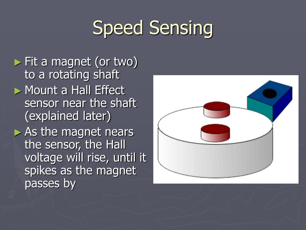
One of the popular applications of hall effect sensors is in automotive systems where they are used to detect position, measure distance and speed. They are also used in modern devices like smartphones and computers and also used in different type of switches where the presence of a magnetic field is used to either activate or deactivate a circuit.

Calculate Speed using Hall effect sensor Circuit Diagram
The GND of the sensor is connected to the GND pin on the Arduino. The Vout or signal pin of the Hall effect sensor is connected to the Arduino's interrupt pin (digital pin 2). Furthermore, a 10K resistor is connected between the VCC and Vout pins of the Hall effect sensor. This is done to pull the output of the Hall effect sensor to 5V.

We will be using the Hall effect sensor and a magnet to find the number of times the car wheel rotated in a minute.The sensor and magnet will be placed in a such a way that at a particular point in every rotation of the wheel the sensor will detect the magnet. One of the draw backs of this code is that the first measurement of speed is

Motor Speed Control Using Hall Circuit Diagram
I've decided to upgrade the car with RPM measurement using Hall sensor and a neodymium magnet. In the following steps I'll describe the parts needed for the setup and will provide the code. I also use the IR remote to change speed of the motor (I change the PWM signal +/-20) to check if the code and the setup is working. Hello, hope you are well. I have a project in electronics in which I need to measure the rotational speed of a fan using a hall effect sensor and display this speed on a 16x2 lcd. I have no problem with the display on the LCD. But I don't know how to go about it with the hall effect sensor to be able to measure the rotational speed of a fan. 3 Phase BLDC with 3x Hall sensors in 120 degrees, 2 pole-pair; The image below shows the situation: I have setup a timer in XOR mode in the micro. The PSC is [19 - 1] and the Counter Period is [10000 - 1] while the timer clock is 80MHz. My motor has the maximum speed of 3000RPM. The timer is setup in XOR mode and with each transition generates