Smart Home Automation System Circuit Diagram
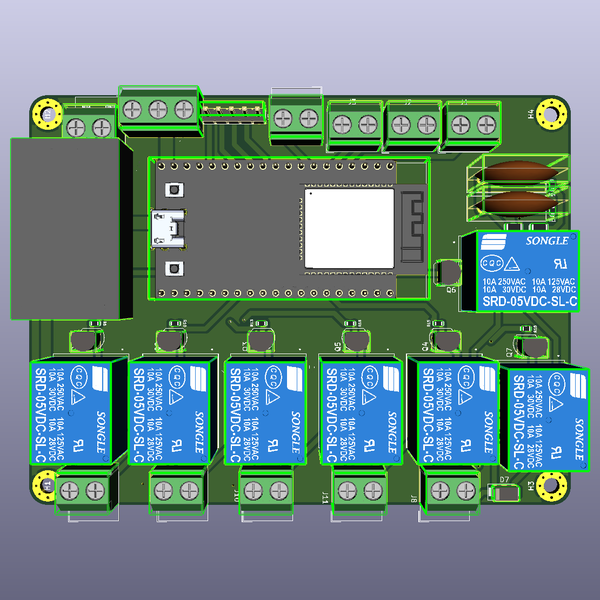
Smart Home Automation System Circuit Diagram This is the complete circuit diagram for this home automation project. I have explained the circuit in the tutorial video. The circuit is very simple, I have used the GPIO pins D1, D2, D5 & D6 to control the 4 relays.. And the GPIO pins SD3, D3, D7 & RX connected with push buttons to control the 4 relays manually.. I have used the INPUT_PULLUP function in Arduino IDE instead of using the pull Here is the list of home automation projects based on various microcontrollers and boards like arduino and raspberry pi. If you are new to smart home automation and are looking to build your first project to control your lights and fans… November 3, 2023 Hammond's modern 1556 series enclosures are designed for circuit boards and IoT

Components Required for Smart Home Automation project. Arduino UNO. HC-05 Bluetooth Module. Relay. Circuit Diagram. Working of Arduino based Home Automation. Project Code. Programming Code Explanation

Smart Home Automation Using Blynk & ESP32 IoT Projects Circuit Diagram
Fig : circuit diagram of Home Automation using Arduino, Relay and Bluetooth Module Interfacing with HC-05 Bluetooth Module It is a small portable device that is used to be connected in the Arduino board so that it can communicate with mobile or smartphone.It has 6 pins, among which we are concerned with only 4 pins.

How to Connect the Bluetooth HC-05 to the Arduino. 1) Connect the Arduino's +5V and GND pins to the bus strips on the breadboard, as shown in the above circuit diagram. 2) Power the HC-05 module by connecting the 5V and GND pins to the bus strips on the breadboard. The HC-05 is powered using 5VDC but includes an on-board voltage regulator that generates a 3.3V supply to power the transceiver.

Home Automation with Blynk & NodeMCU ESP8266 Circuit Diagram
In this home automation circuit, a simple electronic door lock is operated through a sound frequency generated from a mobile app. The mobile app a sound frequency generator set to generate a specific sound frequency. The automatic door lock has a frequency detector which detects this specific frequency for around 3 seconds.
