Overvoltage protection circuit and electronic equipment Circuit Diagram
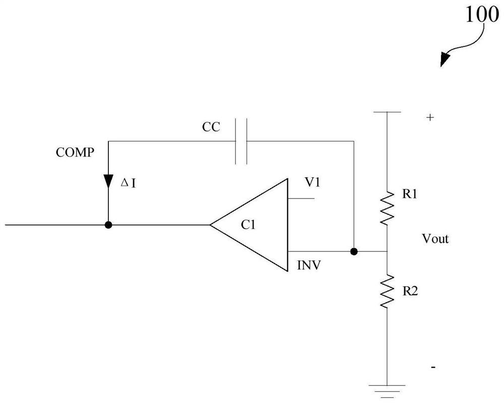
Overvoltage protection circuit and electronic equipment Circuit Diagram A reference is just a low-current reference, it's not designed to power anything. It could be used as part of a protection circuit or part of an over-voltage detection circuit, or part of a regulated power supply, using a comparator to compare the actual power supply voltage with the reference. If you can't find the exact reference you want you
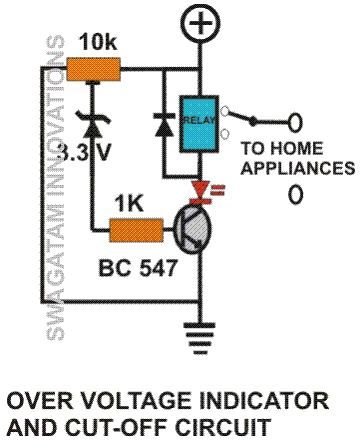
The effects of overvoltage conditions vary from circuit to circuit, ranging from damaging components to degrading component performance and causing circuit failure or fire. By detecting high voltage, the circuit can trigger the thyristor to set a short circuit or shunt on the voltage rail to ensure it does not rise to high voltage. 5
How to design an overvoltage protection circuit? Circuit Diagram
An automatic voltage regulator circuit is a handy electronic device that ensures a steady and optimum voltage supply, protecting the devices from damage caused by under or overvoltage scenarios. In this article, we will guide you through the process of building your own automatic voltage regulator circuit, complete with a detailed diagram.

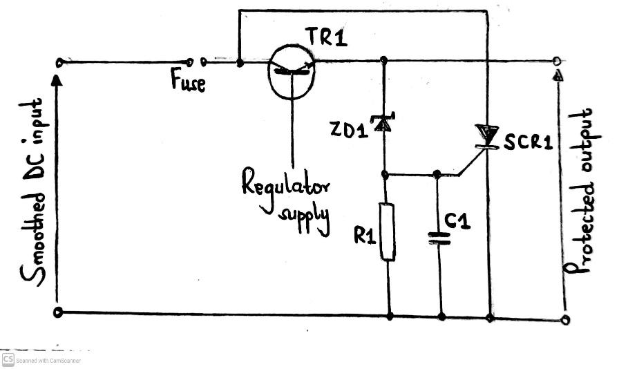
Here simple overvoltage protection circuit is designed by using a Zener diode and transistors. This protection circuit acts as a voltage regulator and also a circuit breaker. you can choose the Zener diode voltage range depending on your load or device voltage range, we have a 5V load and hence we have used a 5.1V Zener diode. Hence, in simple terms, the job of the Crowbar Circuit is to detect the overvoltage and blow the fuse (sometimes, a circuit breaker is tripped). Typically, Crowbar Circuits are designed using Thyristor (SCR) or TRIAC as the main shorting device. Crowbar Circuit Design
[Solved] How to detect overvoltage? Circuit Diagram
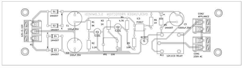
So, we comprehended that both the higher voltages and the lower voltages can do a greater amount of harm to any circuit. Hence, every device needs a voltage protection circuit that can indicate and protect the devices from high or low voltage. Thus, in this tutorial, we are going to Make an "Overvoltage and Under Voltage Protection Circuit"