Electronic Schematic Diagram Circuit Diagram
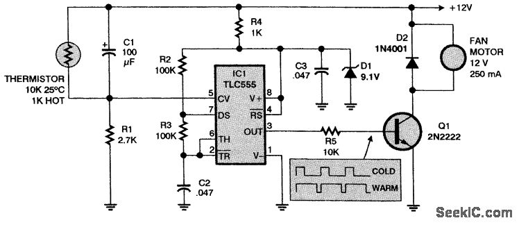
Electronic Schematic Diagram Circuit Diagram This is automatic fan controller circuit project. When sensor system gets hot, this will control speed motor fan is highest. It uses a few components and easily buys at local markets. And easy to build with small PCB. Also, you can modify it to more controls anything as you need with contact of the relay.

The following circuit of a temperature or climate controlled automatic fan speed regulator circuit was requested by one of the followers of Climate Dependent Automatic Fan Speed Controller Circuit. As can be seen in the given diagram, a very simple concept has been implemented in the proposed design of a climate controlled or In this post, we have described how to design Temperature Based Fan Speed Control & Monitoring With Arduino and LM35 Temperature Sensor. The microcontroller controls the speed of an electric fan according to the requirement & allows dynamic and faster control and the LCD makes the system user-friendly. Working of the Circuit: Temperature
Automatic Temperature Control Fan Speed Circuit Diagram
The thermistor used in the circuit here, decreases its resistance with increasing temperature, hence the electrical conductivity also increases, increasing voltage across it, resulting in an increment in the speed of the fan. Thus, it is possible to control the speed of the fan automatically when the device's temperature varies.
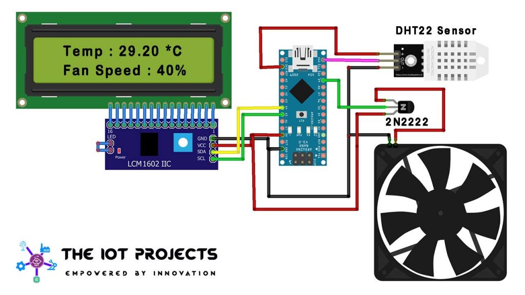
The 2N2222 NPN transistor acts as a controller switch which controls the speed of the fan by using the signal from the Arduino. The IN4007 Diode acts as a protection for the fan from being damaged. When the temperature exceeds the max temp the 5mm LED light glows. Working of the temperature based fan speed controller Circuit
![untitled [www.supercontrol.de] Circuit Diagram](http://www.supercontrol.de/cat/ft847faq/Fan_speed_controller_diagram.jpg)
Building the Perfect Fan Controller: A Step Circuit Diagram
Here the code given is based on the D11 pin as an output. Whenever the temperature sensor detects the changes in temperature outside the Arduino varies the PWM output at the D11 pin, hence the speed of the fan varies. Further in this circuit, the SL100 transistor acts as a switching transistor. And we need a 12V power supply to bias the circuit.

The automatic fan speed control system project can be built with PIC16F877A microcontroller, regulated power supply, LM35, brushless DC motor, LCD, etc. The circuit diagram of the fan speed control system is shown below.In the following circuit, the PIC16F877A microcontroller is used to control the fan speed according to the change in room A fan controller schematic refers to the circuit diagram or design of a fan controller. It outlines the components and connections required to build the fan controller. Advanced features: Pre-made fan controllers often come with advanced features such as temperature monitoring, automatic fan speed adjustment, and fan failure detection