5 Simple Alarm Circuits for Protecting your HomeOffice from Theft Circuit Diagram
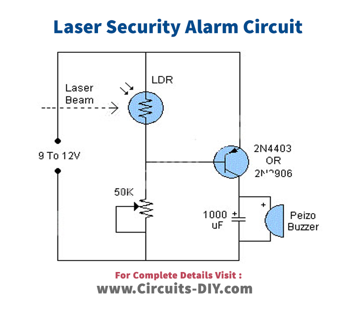
5 Simple Alarm Circuits for Protecting your HomeOffice from Theft Circuit Diagram Enough current now flows through the circuit to trigger the gate of the SCR. Once the gate of the SCR is triggered, current now flows across from its anode to cathode and turns on the buzzer. Once triggered, the SCR stays on, just like an alarm, stimulating an alarm circuit. And this is how this light alarm circuit works.
Below you can see how I connected this circuit on a breadboard: How The Circuit Works. This circuit is very similar to the Automatic Night-Light Circuit. But while the night-light turns on the transistor when it gets dark, this circuit turns on the transistor when it gets light. The photoresistor and the resistor make up a voltage divider.

Light Sensitive Alarm Circuit Diagram
The light-dependent resistor module has four pins: 3.3V : While 'VCC' stands for Voltage Common Collector, we'll connect the VCC pin to 3.3V on the micro:bit GND: In electronics, we define a point in a circuit to be a kind of zero volts or 0V reference point, on which to base all other voltage measurements. This point is called ground or GND. This simple photosensitive alarm activates a buzzer when light shines directly on the connected LDR. The system should be placed on the window at night so that when the light appears in the morning, it will activate the buzzer to alarm. The alarm makes use of a buzzer which is powered by a 9V battery. Read through to understand more. Components: In this Instructables, you will know how to make a Light sensitive alarm. It will be able to detect different amounts of light and then play a song to your choosing. Materials needed:-1 Arduino Uno or any other Arduino-1 LDR (light dependent resistor).-1 buzzer or speakers-1 project box-breadboard and wires
In this video, we'll show you how to create a light-sensitive alarm system using Arduino. This simple yet effective DIY security project will help you detect

Light Sensitive Alarm : 5 Steps Circuit Diagram
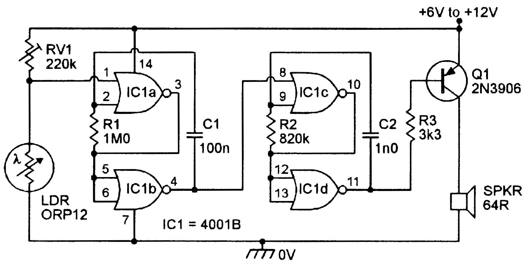
This musical light alarm circuit is very simple, uses only 7 components, a LDR and a 3.6 V battery or 3 x 1.2 volts rechargeable batteries. The well-known UM66 is used as the sound generator and will give a pleasent wake up alarm. As you probably know the LDR is a light dependent resistor. In this video I use a photodiode as the input to an alarm. The circuit remembers if visible light is incident on it, and sets off an alarm to indicate that.